Design criteria: Cast molding
Our basic guidelines for magnesium alloy die casting include important design considerations to help increase the moldability of parts, improve appearance and reduce overall Production time.
Size
Maximum size
| Size | 60 cm. x 40 cm. x 15 cm. |
|---|---|
| Volume | 1575 c㎡. |
| Depth | 15cm from the parting line |
| If the parting line can pass through the middle of the part, the maximum is 20cm. | |
| Estimated mold area | 250 c㎡ |
| Size | 600mm x 400mm x 150mm |
|---|---|
| Volumes | 150mm |
|
Depth |
150mm from parting line |
| If the parting line can pass through the middle of the part, the maximum can reach 200mm | |
| Estimated mold area | 2500 m㎡ |
If the parting line can pass through the middle of the part, the maximum can reach 200mm
Materials
Surface treatment
| Process | Description |
|---|---|
| Chemical treatment | Passivation, micro-arc oxidation, black oxide, painting, powder spraying, sandblasting |
| Power processing | Anodizing, electroplating, gold conductive, electrophoresis |
| Mechanical treatment | Grinding, polishing, wire drawing, laser carving, silk screen printing |
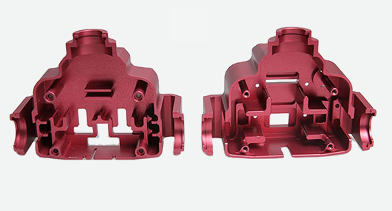
Customized color matching is provided on the number provided by the customer and the part sample provided by the customer.
Mold texturing Applying industry standard textures to molds, you can expect the same effect as mold technology.
Threaded inserts can be achieved through secondary heat melting and ultrasonic welding processes.
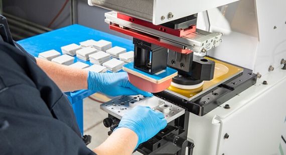
Padding Transfer a two-dimensional image (such as a company logo) to a three-dimensional object.
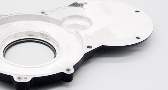
Laser engraving is applied to molds or directly to final parts to obtain information such as part numbers.
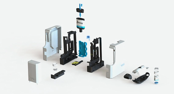
Basic assembly includes fastening the molded parts we make together and/or attaching labels to individually packaged parts.
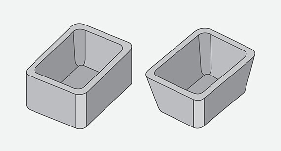
Draft
| Vertical plane |
0.5° |
|---|---|
| In most cases |
2° |
| Minimum Close | 3° |
| Minimum light texture (PM-T1) | 3° |
| Minimum light texture (PM-T2) | 5°+ |
Undercut
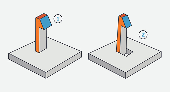
Maximum side core size
| Width | Height | Length |
|---|---|---|
| < 21.3 cm. | < 6.88cm. | <0.366 cm. |
Maximum side core size
| Width | Height |
Length |
|---|---|---|
| <213.00mm | <60.88mm | <3.66mm |
Wall thickness
Materials
| Materials | Minimum wall thickness |
|---|---|
| AZ91D | 1100mm x 800mm x 500mm |
| ZK61 | 1100mm x 800mm x 500mm |
| AZ31 | 1100mm x 800mm x 500mm |
| AZ61 | 1100mm x 800mm x 500mm |
| AM60 | 1100mm x 800mm x 500mm |
| Other materials | 1100mm x 800mm x 500mm |
| Customer provides materials | 1100mm x 800mm x 500mm |
* This table is adapted from www.cyanbat.com.
|
Materials |
Minimum wall thickness |
|---|---|
| AZ91D | 10mm x 20mm x20mm |
| ZK61 | 10mm x 20mm x20mm |
| AZ31 | 10mm x 20mm x20mm |
| AZ61 | 10mm x 20mm x20mm |
| AM60 | 10mm x 20mm x20mm |
| Other materials | 10mm x 20mm x20mm |
| Customer provides materials | 10mm x 20mm x20mm |
* This table is adapted from www.cyanbat.com.
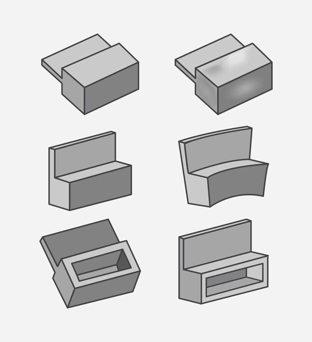
The first line: Design a part with thicker features, and the resulting sink after molding. Middle row: shows parts designed to have thicker features.
Bottom: Demonstrates how to remove thicker features to help create well-formed parts.
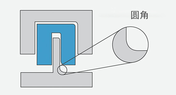
Radius
Because we use automatic CNC milling process to make part molds, the corners of some parts will have radii instead of sharp edges. This usually does not require changes to the model, but the resulting radius can be determined before milling the mold.
