Design criteria: CNC turning
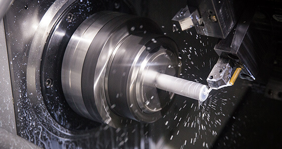
Our basic guidelines for CNC turning include important design considerations to help improve part manufacturability, improve appearance and reduce overall production time.
size
biggest size
| Mg | 26cm. |
|---|---|
| Al | 32cm. |
| stainless steel | 36cm. |
| length | 110cm. |
| Mg | 260mm |
|---|---|
| Al |
320mm |
| stainless steel |
360mm |
| length | 1100mm |
smallest size
| diameter | 0.016 cm. |
|---|---|
| length | 0.02 cm. |
| Wall thickness | 0.0025 cm. |
| angle | 30° |
| diameter | 0.1mm |
|---|---|
| length |
0.2mm |
| Wall thickness |
0.25mm |
| angle |
30° |
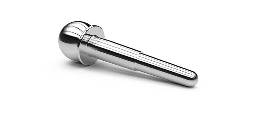
Small features may be allowed, but the diameter of any area should not be less than 0.76 mm. A sharp conical tip is allowed; the angle should be greater than 30 degrees. Walls thinner than 0.5 mm usually cannot withstand the effects of the machining process. Regarding the specific turning size according to the material, the maximum range of parts processed
Generally, CYANBAT Technology can maintain a machining tolerance of +/- 0.13 mm.
Real-time tool function
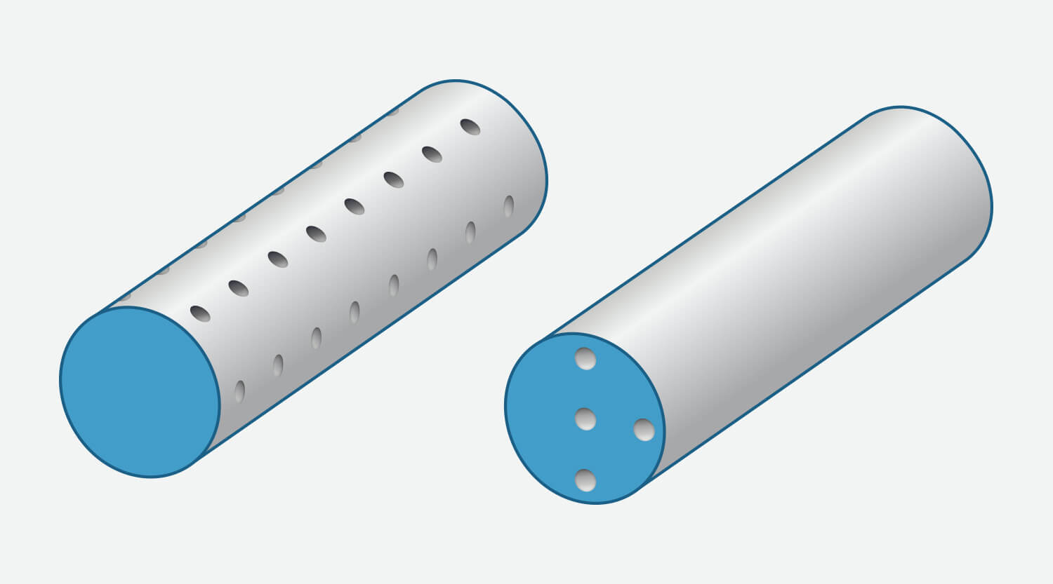
Our lathes contain powered tools to add additional milling features to the turned parts, including planes,
grooves and grooves. We can also add axial, axial and radial holes to the turned parts, but only the holes that are parallel or perpendicular to the rotation axis can be supported, and for hard metals, we cannot accommodate odd-angled holes.
We can mill off-axis holes in turned parts made of aluminum or brass.
CNC machining surface finish guide
Get a true snapshot of the surface finish that can be done on machined plastic and metal parts.
View >
Design points of CNC machining
We have compiled some of the best design techniques to help you optimize the design of CNC machining parts..
View >
material
- AZ91D
- ZK61
- AZ31
- AZ61
- AM60
- Customer Provided
Surface treatment
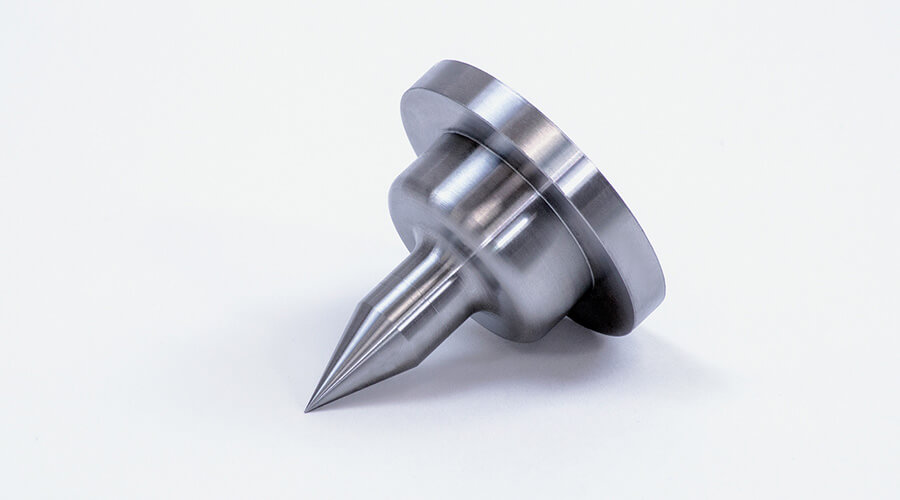
Turned parts usually have a very smooth surface finish. When using a lathe, the surface finish of the cylindrical area after machining is usually much smoother than that of a milling machine. Therefore, please take this into consideration when choosing a processing method for parts suitable for either method. Areas cut with active tools (for example, plates and notches) may have visible tool marks. If needed, The metal parts can be slightly sandblasted to retain a good matte effect. Hard metals such as steel and stainless steel can also crack the edges (deburring) by lightly grinding the beads, To remove metal fragments and sharp or rough areas.
| magnesium alloy | Edges damaged by visible tool marks, edges damaged by light-colored beads blasting, or sharp edges with visible tool marks |
|---|---|
| Other metals | The edge is broken by visible tool marks or the edge is broken by light bead jet |
Threaded hole
We currently support UNC and UNF threads, from #2 to 0.5 cm. , And metric threads from M2 to M12. Avoid modeling internal threads in part design.
radius
As a natural result of the CNC machining process, sharp internal corners on the part will be rounded (rounded). The resulting radius will be determined before milling the part. The outer corner of the turn will usually contain a 0.005cm chamfer.
Holes and grooves
We can add axial, axial and radial holes to the turned parts, and we support holes parallel or perpendicular to the axis of rotation. Eccentric holes are used for turned parts machined from aluminum and brass.
Text on part
Currently, text is not supported on turned parts.
Minimum hole size:
- Coaxial and axial:1mm
- Radial: 2mm, magnesium alloy and aluminum alloy 1mm
Groove:
- Minimum outside diameter groove width: 1.2mm
- The minimum outside diameter groove width of magnesium alloy/aluminum alloy: 0.5mm
- Maximum outer diameter groove depth: 24.1mm—varies with groove width
- ID groove is not currently supported
